|
This
page
outlines the procedures for replacing the computer chip on an S2 with a
"performance" chip.
At the
recommendation
of several fellow S2 owners, I decided to order the chip .
The
chip has been described
as being a Welmeister clone.
(I suppose
that means
that it performs like the Welmeister chip.)
This is
what I have
been told about the chip:
- it
adds roughly 15 horsepower
- overall,
the timing is
advanced a little, with a little more advance above 4500 rpm
- the
mixture is richened
a little bit
- the
rev limiter is raised
to 7000 rpm, which is supposedly still safe for an S2
- overall
driveability is
improved i.e. it feels much better at all speeds and rpms
Disclaimer:
These
instructions and pictures are intended as a guide, to help fellow S2
owners
with assistance in installing a performance chip in their vehicle. Read
these instructions carefully, look at the pictures closely, and TAKE
YOUR
TIME!! It took me roughly an hour and a half to finish the job, with my
being very careful and not hurrying. If you are not comfortable with
doing
this type of work on your vehicle, DON'T DO IT!! Take it to someone you
trust instead, or just don't do the upgrade!! I assume no
responsibility
if YOU screw up your car!! I hate to state it this way, but the lawyers
in this country have made just about everyone paranoid about liability!!
Note:
Electronics
such as this are components that are very sensitive to static
electricity.
Be conscious of this as you perform this process. Some recommendations
I had received were:
- disconnect
the negative
battery terminal (I did not do so, but the choice is up to you!!)
- wear
a grounding strap
- ensure
that you ground
yourself before opening and working with the inside of the "brain"
At the end
of this page,
I've included the detailed instructions that these fine gentleman had
provided.
They are what I used when I installed the chip. Print them out, along
with
this page (with pictures), and use both to ensure that the installation
process goes smoothly and quickly!! Good luck and have fun!!
The
"brain" of the
S2 is underneath the passenger side carpet.
Pull back
the carpet,
and you'll find a wooden panel. There are four screws holding it in
place.
Remove them.
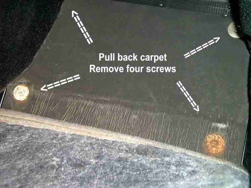
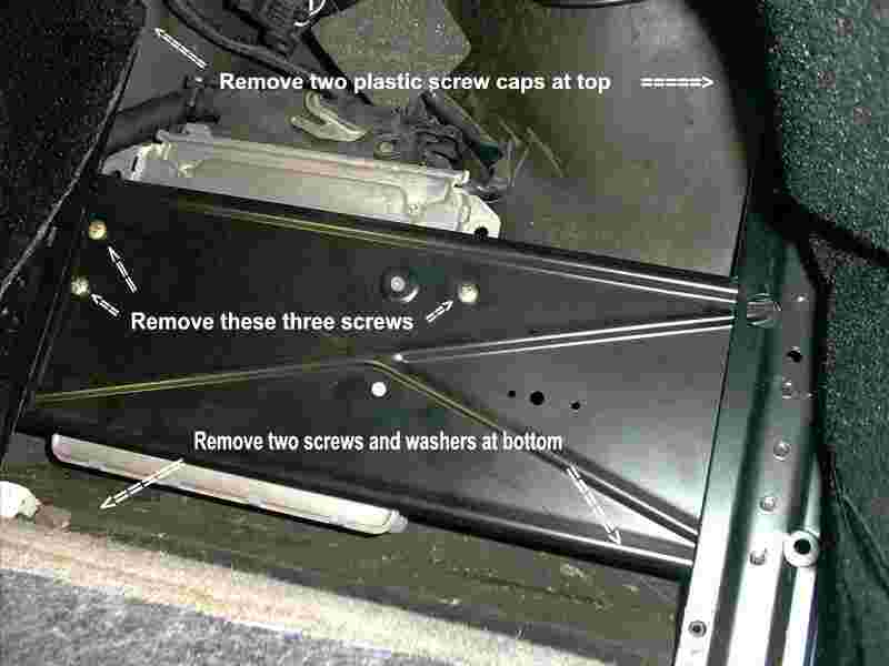
This
picture shows
what you see next. Remove all of the screws as noted in the picture.
I found it
easier
to remove all of the screws, to make the frame loose enough to get the
"brain" out.
I did not
remove the
black frame, I just loosened it.
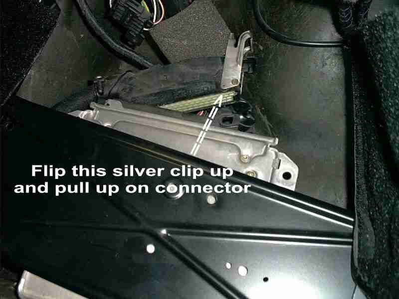
Flip up
the silver
connector on the top of the "brain".
This
disconnects the
wiring harness from the brain.
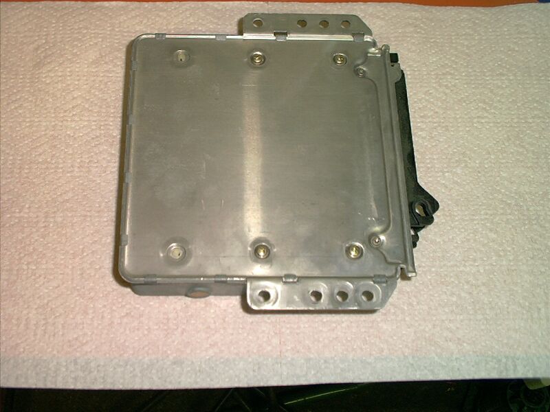
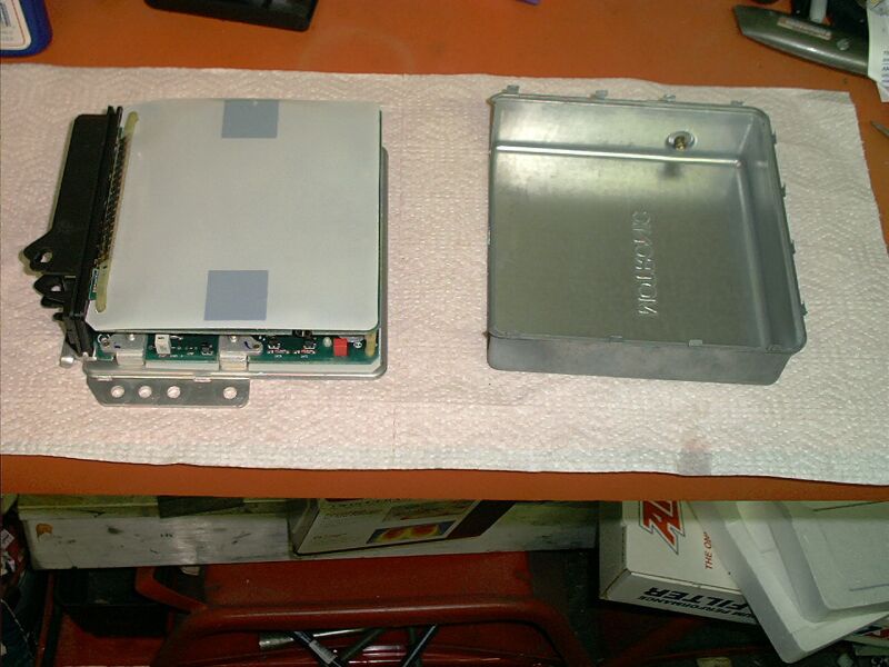
Here is
the "brain"
removed from the car.
Pry up on
all of the
small tabs around the edge.
I used a
small eyeglass-type
screwdriver to get underneath them enough to get a bigger screwdriver
underneath.
Then remove
the four
screws holding the cover on.
Here is
the "brain"
with the cover removed.
You'll see
that there
are two circuit boards that must be separated.
Carefully
pull up
on the back end to separate that end of the two boards.
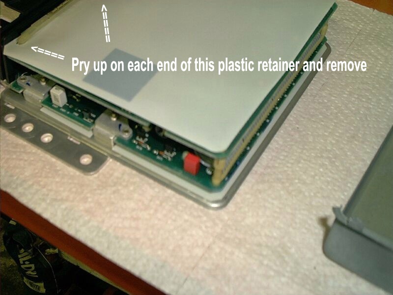
At the
front end, pry
up gently and remove the plastic connector holding the top board to the
bottom board.
Note how it
was installed,
for reassembly purposes.
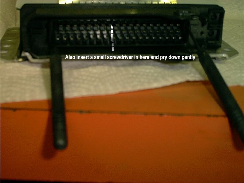
Here is
the "connector"
end of the "brain".
Stick two
small screwdrivers,
or paper clips or something similar into the two ends, to help unclip
the
top board.
And then
stick another
screwdriver or such into the middle, prying gently to also separate the
top board from the connector end.
While doing
all that,
pull back gently on the top board.
This may
sound confusing,
but once you take a closer look at it, you'll understand.
(Yes, you
could really
use three hands for this... but it is possible for us humans with only
two!! Just be careful and take your time!!)
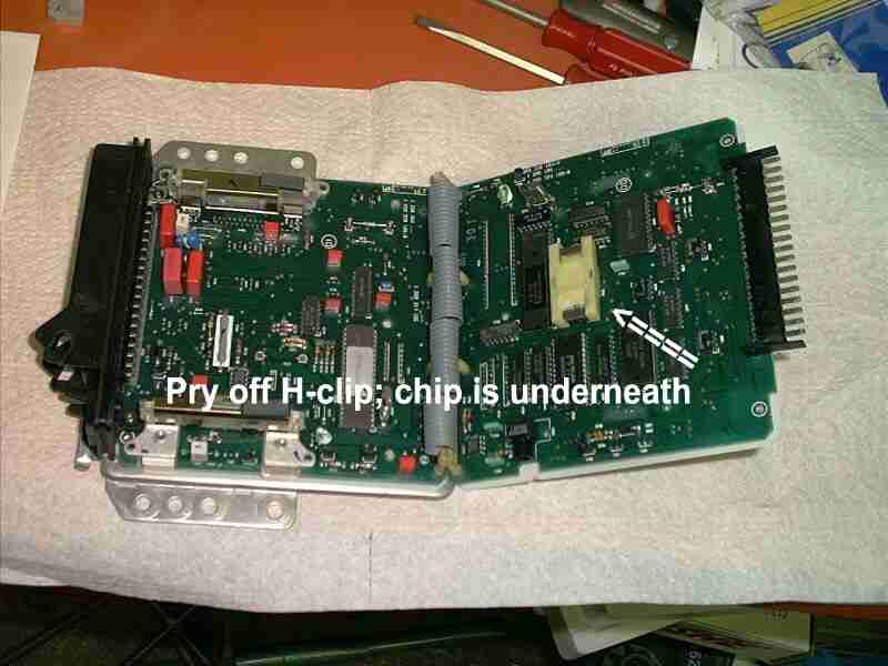
Here is
the "brain"
fully exposed!!
The chip is
underneath
the plastic H-clip.
Gently pry
up on the
H-clip to expose the chip.
Once
exposed, gently
pry up on the chip. Be careful to only pry up on the chip itself, not
the
circuitry that it is plugged into!!
Given that
the new
chip's "legs" may not be perfectly lined up, you may need to bend them
slightly. If so, at a 90 degree angle to a hard surface, gently bend
them
in slightly.
Install the
new chip,
ensuring that it is pushed all the way down and that it is secure.
And then,
don't forget
(like I did!!) to re-install the H-clip over the new chip.
To put it
all back
together, reverse the order of these procedures.
After
putting everything
back together, start the car, and take it for a test drive!!
As everyone
else who
has installed one of these chips can also attest, be prepared to notice
a difference immediately!!
The
performance gain
is subtle, but noticeable. It is well worth the small amount of money
Here
are the
procedures summarized by Michael Stephenson as posted on the Rennlist
S2
mailing list as well as the Rennlist S2 forum.
Be sure to
read the
additional method below from Tom Boerger for separating the boards; it
is much easier and highly recommended to avoid potential damage.
This is
the additional
information from Tom about separating the top board at the connector
end.
"I was
able to get
the top board flipped over after some more effort. The thing I was
missing
was the small "lip" at the front of the top board that hooks around the
front of the attachment point. You were able to get around this by
raising
the back of the top board..... thus lowering the lip enough to
clear....
the other way to do it is to use a third screwdriver.... two for the
clips
on the side of the front mounting point, and one at the top prying down
to bend the "lip" so it will clear. Using the 3 screwdriver method, the
board pulled straight out no problem".
|